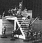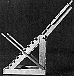
This item was inspired by the attack tower in the movie The War Lord. While I have built more elaborate towers in the past, I have found this one to be the most practical of the lot as it does not look out of place when used against the smaller fortifications whicn I prefer to use in my games.
You will also find that a WRG 60 mm stand will fit nicely (with a little overhang on each side) and two stands may actually be mounted on the ladder prior to the assault and another two on the bridge during the assault itself.
The entire structure is built of popsicle sticks (available from arts and crafts stores in packages in an unused condition) and round dowels, about 1/16 inch in diameter (from long throat swabs at the drug store). A bit of string is used for the rope supports for the bridge and rollers or wheels may be cut from large diameter dowel (wheels or rollers not illustrated to avoid ciuttering up the diagrams).
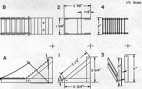
Diagrams A and B are side and front views of the completed tower. The two crosses on the face of the tower in B are archer's firing slits and are optional. Loopholes are easier to make or leave them out entirely.
 In all diagrams the heavy solid lines represent the small dowels and dotted lines show continuations of pieces that would be hidden from view.
Diagram 1 is the basic side frame. Make two of these. Note that the horizontal bottom piece is glued to the outside of the vertical and sloped pieces. This means that you will be making a left hand and right hand vertical side so that when assembled the horizontal pieces are both on the outside. The angled cuts on the "hypotenuse" piece are easiest done by laying that piece over the others after they have been positioned and then marking the angles for the cuts. Diagram 1 is a left side frame.
Diagram 2 puts us under the base, looking up. You simply add a piece of planking across the front of the base and another parallel to the ground across the top of the lower frame just forward of the sloped hypotenuse'' pieces. See sketch A, if you are not quite sure where this piece belongs.
Continue planking up the front except at the very top where one plank must be left off or the bridge won't be able to drop properly. All planking is 1 3/4 and the axle and ladder rungs are all 2 inches long. If you have a small vise clamp a bunch together and cut them all at once in batches. Use a hobby saw with fine teeth. The ladder rungs may be glued on now, use ten or eleven of these.
Diagram 4 is a rear view of the tower ladder. For approximate spacing work off of diagram A as diagram 4 does not take the slope into account.
Diagram 3 shows the construction detail for the bridge. The decking extends over either side of the supports. A piece of dowel is glued on either side of the supports, under the decking, one on each side. Start it forward of the axle hole and extend it beyond the end of the bridge so that the two will rest on the wall being assaulted when the bridge is lowered. Make these extra long if you like and tie a small bundle of straw across the two which would be set afire just prior to dropping the bridge to drive the defenders back as the assault is made. Not too much straw or the bridge and/or storming party may catch fire as well. [I suggest that you only simulate this. Ed.]
The two angled dowels seen in diagram A are about 3 and 1 inches long respectively, two of each. The longer pair takes the end of the rope which has a large loop fashioned at the end (coat with clear nail polish or Elmer's glue for rigidity and durability and allow to dry before slipping into position) which is slipped off the poles to drop the bridge.
The shorter pair are push poles to aid the dullards assigned to push this monstrosity into position. Both sets of poles also act as supports for the ends of the stands of figures positioned on the ladder. The front edge of the stand fits between the rungs of the ladder and makes the stand quite secure.
The holes for the axle for the bridge can be a little oversized. Use a small drill and then a round needle file until you have it the way you want it. If the bridge tends to fall backward, lengthen the drop ropes a little so the bridge leans slightly forward, gravity and the ropes will then hold it in the desired position.
For glue, use a fast setting contact cement while positioning pieces, then go back over the critical spots with Elmer's or something similar for a good hard bond. The contact cement I use is Walther's Goo which is found in most model railroad shops. Don't worry about getting all the lengths of plank and dowel exactly even. In real life, this thing was built in a hurry for a one-time job so neatness doesn't count.
if the tower is not tall enough for the particular wall being assaulted you can vary the dimensions, make large rollers or build an earthen ramp to equalize the height. You will find that because of the way the bridge is dropped you already have a bit of latitude built in as the bridge does not have to be perfectly level for the assault column.

Back to Table of Contents -- Courier Vol. 1 #2
To Courier List of Issues
To MagWeb Master Magazine List
© Copyright 1979 by The Courier Publishing Company.
This article appears in MagWeb (Magazine Web) on the Internet World Wide Web.
Other military history articles and gaming articles are available at http://www.magweb.com
